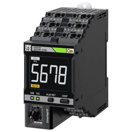
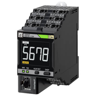
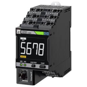
K6CM-CI2M
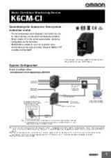
Motor Condition Monitoring Device – current monitoring
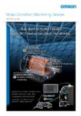
K6CM-CI2M is a reliable partner allowing you to plan in advance your maintenance interventions on-Three-Phase-Motors, avoiding costly downtime and lost production.
K6CM-CI2M controller monitors current waveform and spectrum as very effective indicators of the entire motor’s driveline health status, suggesting maintenance whenever any deviation from normal behaviour is detected, before serious issues occur.
Current-based condition monitoring allows to:
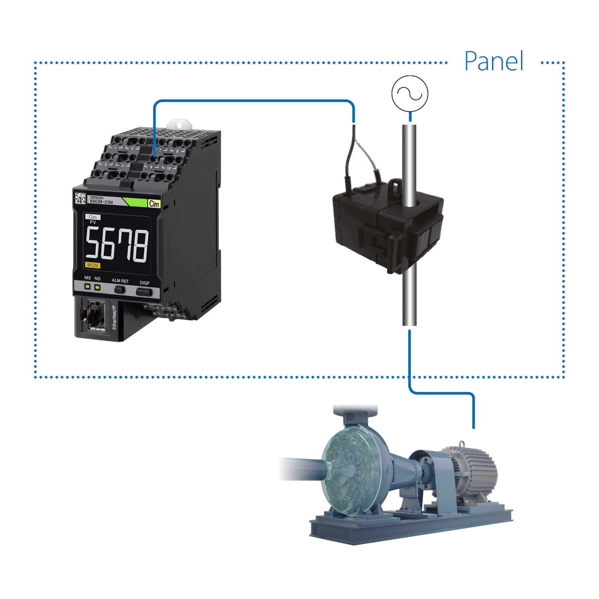
- Install the controller and the current clamp in the panel, without the need to wire sensors on the motor. K6CM-CI2M is the best solution for motors and pumps that are either submerged or located in clean rooms, HVAC systems, in existing machines or inaccessible locations.
- Have a comprehensive monitoring of the whole driveline’s status. Anomalies, such as pump cavitation, load unbalance, misaligned belts, rotor and stator issues in fact, are proven to cause anomalies in the absorbed current’s waveform and can be easily detected with this method, even before changes in vibrations can be detected.
- Setup the system in few minutes through user-friendly software, as the parameters setting is very simple and the analysis algorithm is embedded into the controller.
- notifications in case of warning/alarm,
- remote monitoring
- interaction with custom applications and MQTT server.
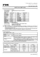
Specifications & ordering info
| Produkt | Supply voltage AC | Supply voltage DC | Description | |
|---|---|---|---|---|
|
|
100-240 V | Motor Condition Monitoring, AC, 3-phase, Induction motor, Current Analysis model, 100 to 240 VAC, Transistor control output, Push-in Plus, LCD display, Ethernet IP/Modus, applicable in environment with inverters |
|
|
|
|
20.4-26.4 V | 20.4-26.4 V | Motor Condition Monitoring, AC, 3-phase, Induction motor, Current Analysis model, 24 VAC/VDC, Transistor control output, Push-in Plus, LCD display, Ethernet IP/Modbus, applicable in environment with inverters |
|
Need assistance?
We’re here to help! Reach out, and our specialists will assist you in finding the best solution for your business.
Kontakt mig K6CM-CI2M
Tak for indsendelsen af din forespørgsel. Vi vil vende tilbage med svar så hurtigt som muligt.
Vi har desværre tekniske problemer. Din formular er ikke modtaget. Vi undskylder og beder dig om at prøve igen senere. Detaljer: [details]
Tilbud på K6CM-CI2M
Med denne formular kan du bestille et tilbud på et eller flere af vores produkter. Venligst udfyld alle de felter der er markeret med *. Dine personlige oplysninger vil blive håndteret fortroligt.
Tak for din forespørgsel. Vi vender tilbage med de ønskede oplysninger så hurtigt som muligt.
Vi har desværre tekniske problemer. Din formular er ikke modtaget. Vi undskylder og beder dig om at prøve igen senere. Detaljer: [details]
Feature
K6CM-CI2M can be easily installed in existing machines, as there is no need to wire the motor/pump.
Controller and current clamp are located in the panel.
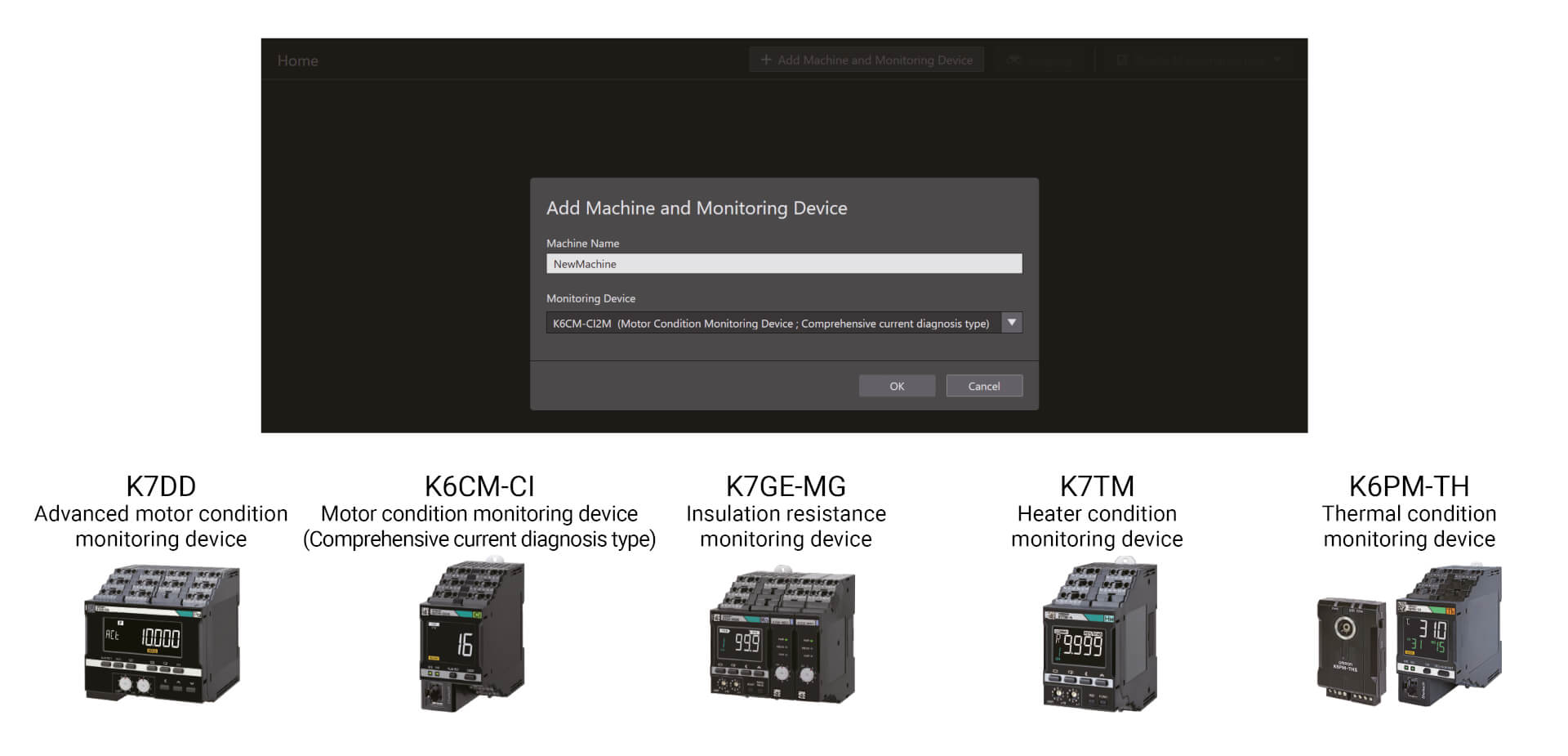
Condition monitoring devices can be configured with a single tool
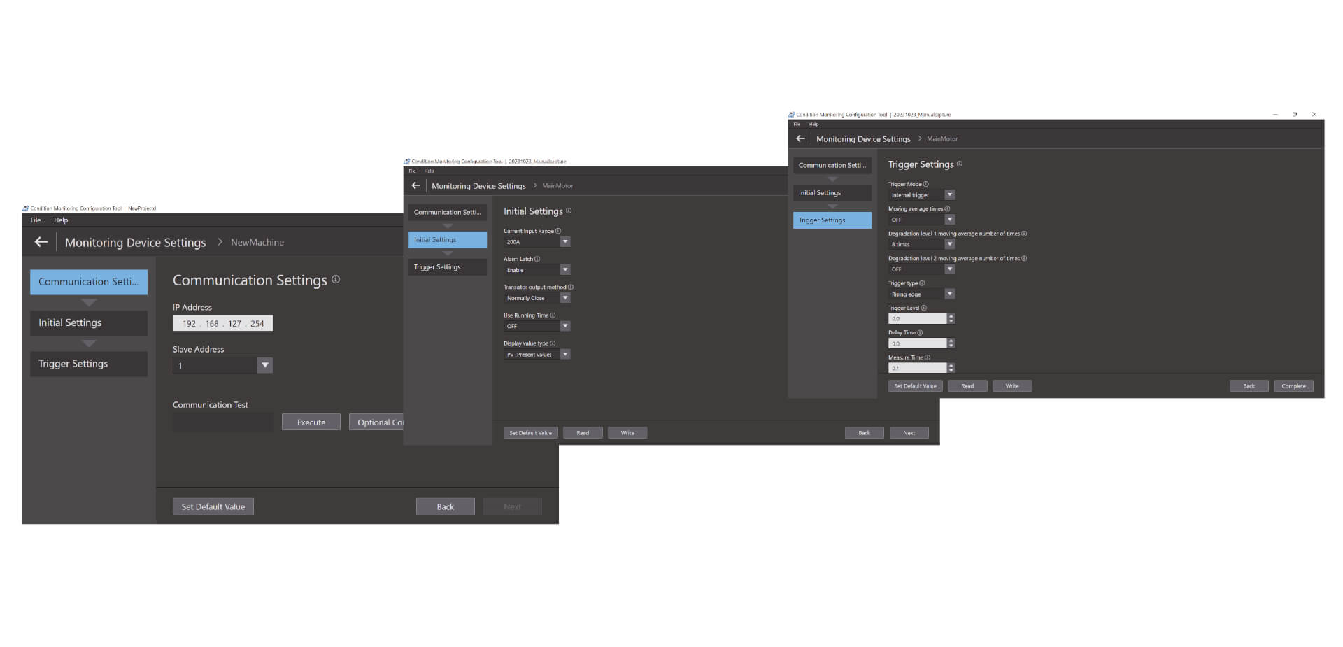
Easy three-step configuration The Condition Monitoring Configuration Tool allows for batch configuration of a wide range of condition monitoring devices, such as those for monitoring motors, temperatures, insulation, and heaters. It can be used without any special skills, reducing training effort
Easy three-step configuration
The Condition Monitoring Configuration Tool allows for batch configuration of a wide range of condition monitoring devices, such as those for monitoring motors, temperatures, insulation, and heaters. It can be used without any special skills, reducing training effort. Setup can be completed in just three steps: communications setup, initial setup, and trigger setup.*1 With its high operability, the tool boosts on-site productivity as well.
Videos

-
K6CM Motor Condition Monitoring Device
K6CM takes the burden of monitoring motors off maintenance engineers. Motors can be maintained in advance of failure due to deterioration. K6CM (comprehensive current diagnosis type) can consistently monitor motor conditions by observing the current waveform of the motor. Additionally, you can understand the motor's maintenance timing without depending on an engineer, because K6CM provides threshold value setting.
02:40
K6CM Motor Condition Monitoring Device
K6CM takes the burden of monitoring motors off maintenance engineers. Motors can be maintained in advance of failure due to deterioration. K6CM (comprehensive current diagnosis type) can consistently monitor motor conditions by observing the current waveform of the motor. Additionally, you can understand the motor's maintenance timing without depending on an engineer, because K6CM provides threshold value setting.
-

K6CM Demo Video
05:48
K6CM Demo Video


OMRON K6CM Conveyor Chain Demonstration Video


OMRON K6CM Misaligned Drive Belts Demonstration Video

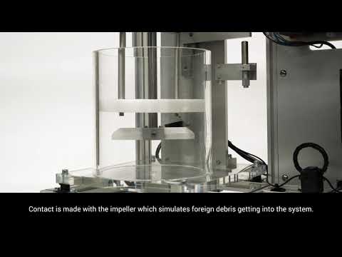
OMRON K6CM Mixer Demonstration Video


OMRON K6CM Pump Cavitation Demonstration Video


OMRON K6CM Spray Dryer Demonstration Video
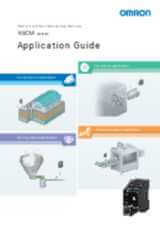
Solutions
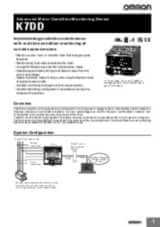
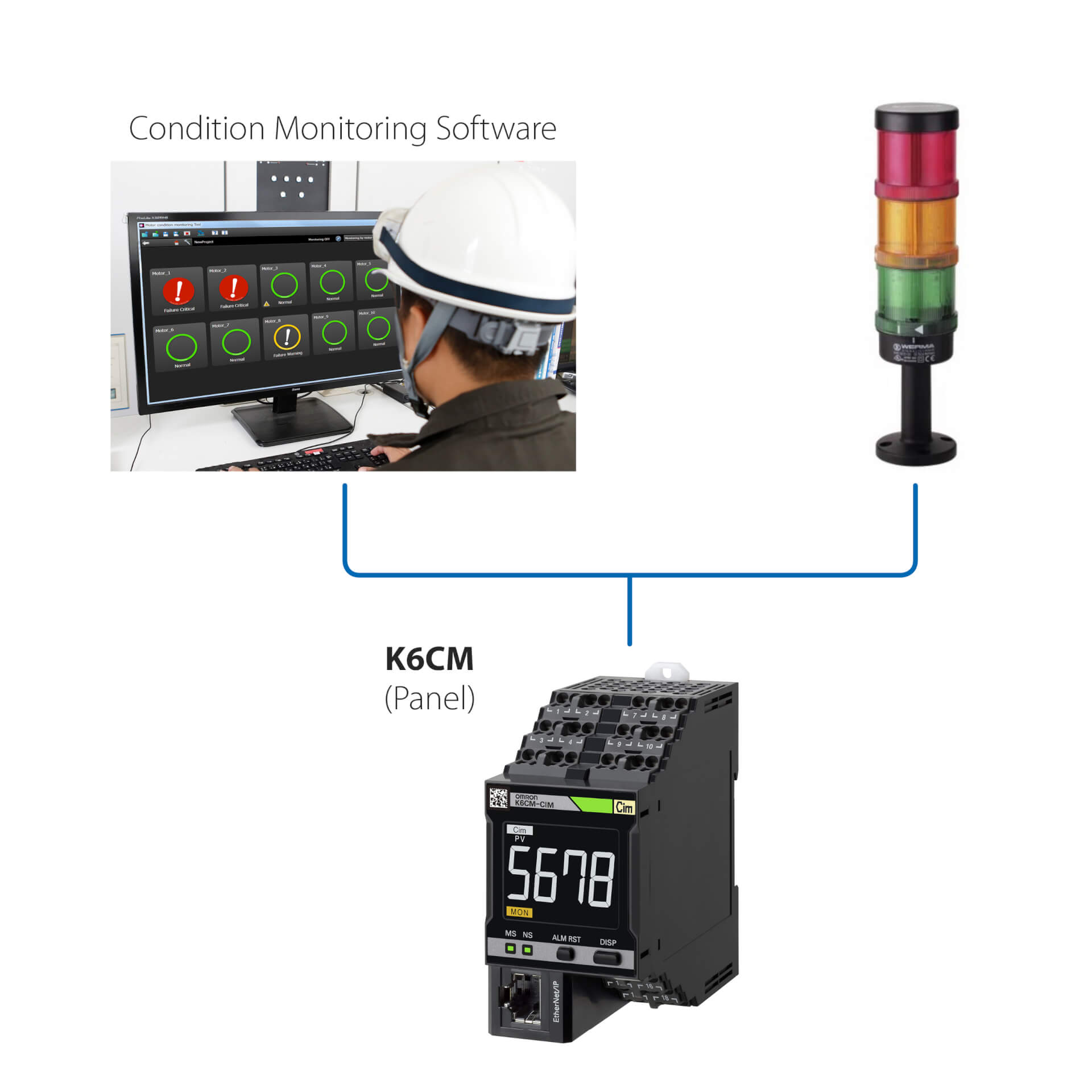
Stand Alone installation (Without PLC)
This simple solution allows to:
- Monitor the status of the motor through the onboard LED, or through to the Condition Monitoring Software
- Setup the controllers through the Condition Monitoring Software, provided with the device
- Interface the K6CM with any external I/O devices (dig. Output)
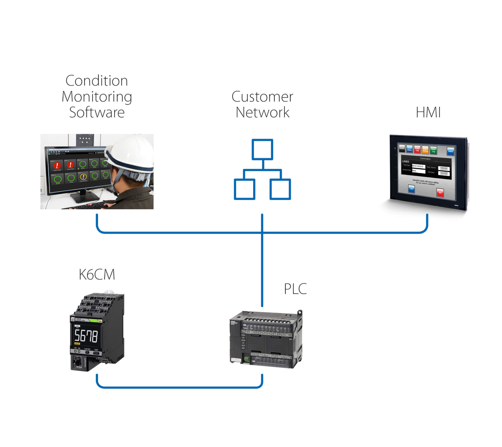
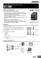
Stand Alone installation (with PLC)
This solution enables, in addition of the previous solution, to:
- Monitor the status of the motor through to the Condition Monitoring Software, running on a PC which is connected through a PLC
- Trigger, through the PLC, actions following any warning/alarm detected by K6CM
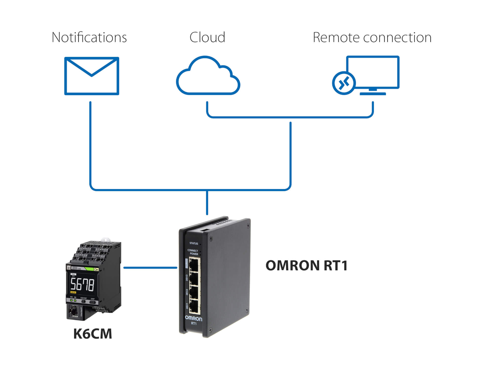
Notifications and remote monitoring - without PLC
This solution, using Omron RT1 as a gateway, enables:
- e-mail/SMS notifications in case anomalies are detected by K6CM
- secure connection (managed by RT1) to cloud, either via LAN or via 4G connection
- secure connection for remote monitoring and setup of K6CM, using the Condition Monitoring software provided with the controller
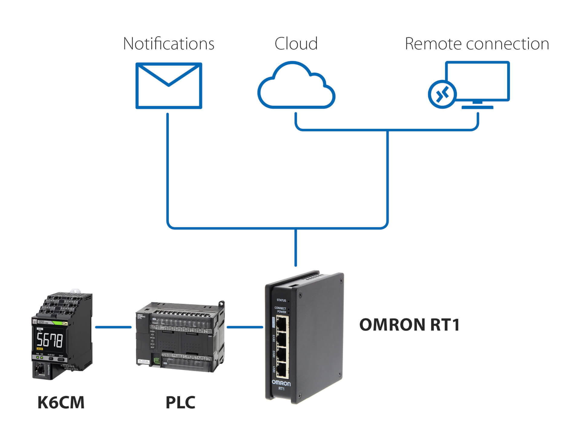
Notifications and remote monitoring – with PLC
This solution, using any PLC and Omron RT1 as a gateway, enables:
- e-mail/SMS notifications in case anomalies are detected by K6CM
- secure connection (managed by RT1) to cloud, either via LAN or via 4G connection
- secure connection for remote monitoring and setup of K6CM, using the Condition Monitoring software provided with the controller
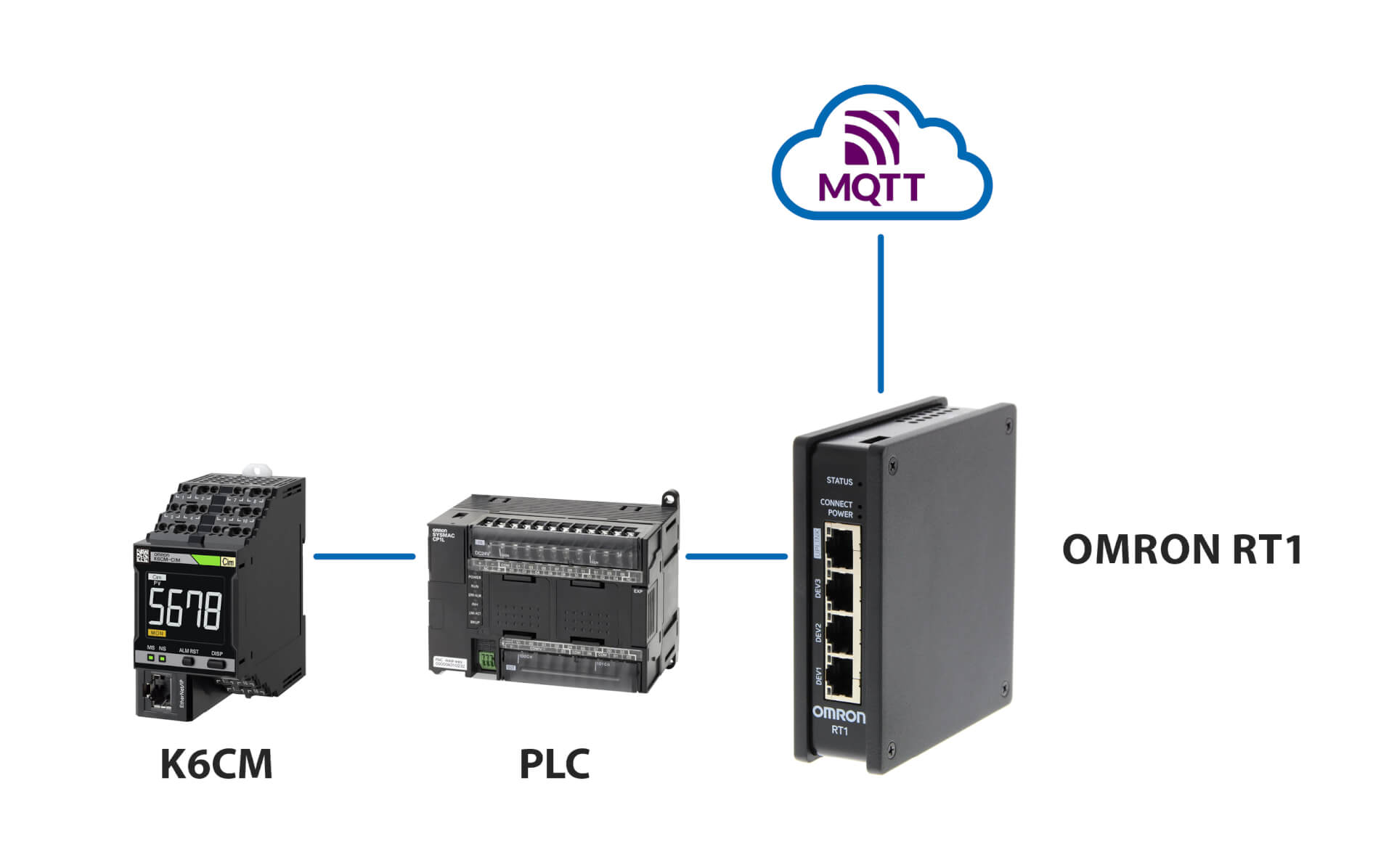
Connection to MQTT server
Relaterede produkter
-
Motor Condition Monitoring Device – insulation monitoring
-
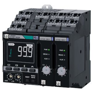
Motor Condition Monitoring Device – vibration monitoring
-
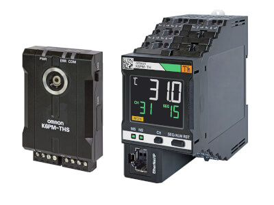
Thermography-based Condition Monitoring
-
Condition Monitoring Device – insulation monitoring
Downloads